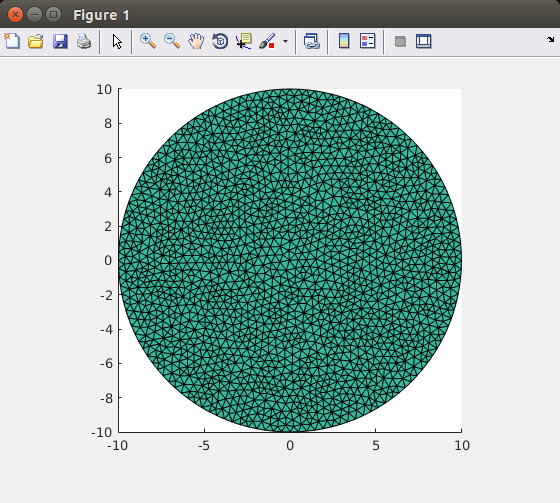


Data Geometrical Tolerance: The geometrical tolerance for the mesh to match the object edges.This property can also be changed in the Gmsh dialog in the field Mesh order. Data Element Order: The mesh element order.From Shape (default) the dimension will be determined from the dimension of the object that is meshed.This property can also be changed in the Gmsh dialog in the field Mesh element dimension. Data Element Dimension: The dimension of the mesh elements.true (default) duplicate mesh nodes will be removed.This property can also be changed in the Gmsh dialog in the field Min element size. If set to 0.0, the size will be set automatically. Data Characteristic Length Min: The minimal size of the mesh elements.This property can also be changed in the Gmsh dialog in the field Max element size. Data Characteristic Length Max: The maximal size of the mesh elements.The different algorithms are explained here. Data Algorithm3D: The algorithm to create 3D meshes.For Delaunay, see Delaunay triangulation.

#Volume mesh in gmsh code#
One possible solution is to write a code using Mmg that does this, but this requires dealing with the Mmg data structures. We are interested to extract different regions into separate mesh files while preserving the surface sets. These kinds of mesh files are commonly found in the output of code-based mesh generation processes, i.e you generate a mesh using a mesh manipulation or computational geometry library such as Mmg (used to generate the mesh below) or CGAL.Īs can be seen in the figure (visualized using GMSH), in addition to several surfaces and curves, there are 2 volume sets in the generated mesh. Lots of mesh generation routines may result in a multi-region mesh, out of which you want to extract a certain region (block). Separating different volume mesh blocks (regions) using FreeFEM


 0 kommentar(er)
